Short answer: Yes. With the free, open source text-to-cad plugin, Claude Code writes Python that builds a real solid with exact millimetre sizes, then exports STL or 3MF files your slicer can print. It also measures walls and overhangs before you waste plastic. You still need to check the result with numbers, not just a picture.
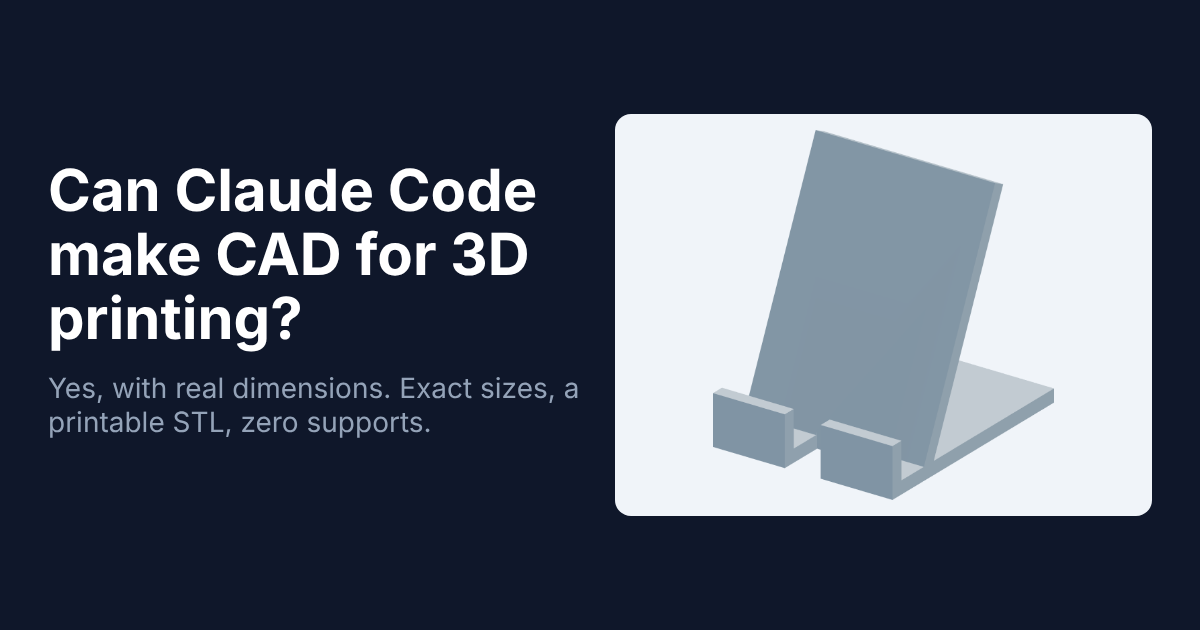
That check is the point of this post. Say you ask an AI for a phone stand. You get back something that looks like a phone stand. Then you print it, and your phone does not fit in the slot.
That gap is the whole story. A shape that looks right and a shape that is right are two different things, and only the second one is useful on a printer.
So here is what I wanted to know: can an AI coding agent give you the second kind? I installed text-to-cad, built a real part with it, ran its print checks, and made one mistake along the way that taught me more than the part did.
What is the difference between an AI 3D model and CAD?
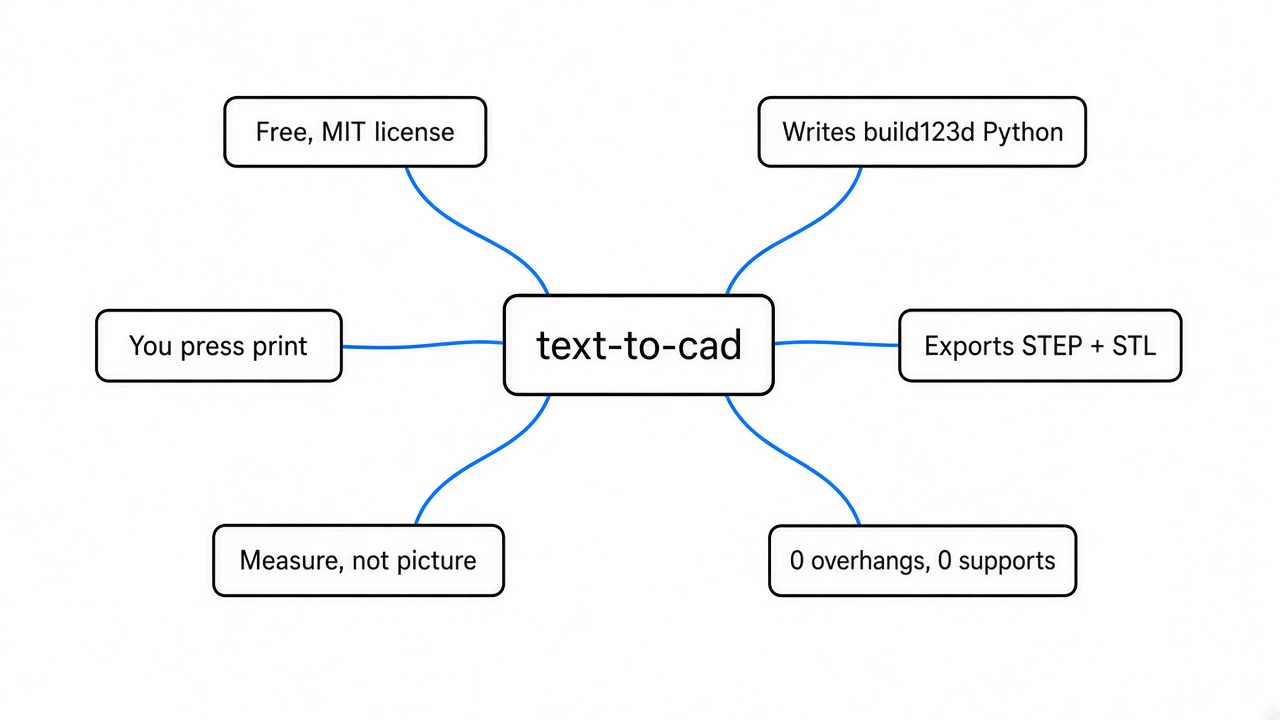
Most “AI 3D model” tools make a pretty skin. CAD makes a solid with exact sizes.
To see why, start with the basics. A 3D printer needs a file that describes a closed shape. The most common one is STL (a file that describes a shape as thousands of tiny triangles).
Most text-to-3D tools produce a mesh (a surface made only of those triangles). A mesh is like a plaster cast of an object. It shows the outside, but nobody wrote down how wide anything is, so the sizes are whatever came out.
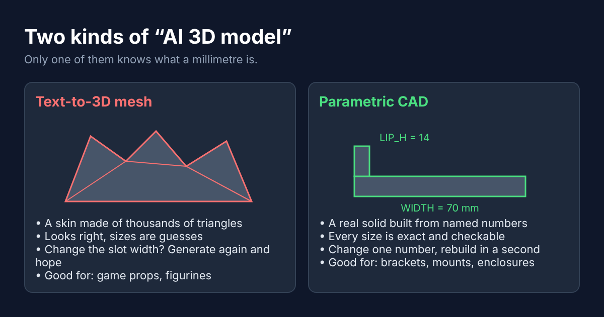
Real CAD (Computer-Aided Design, the software engineers use to design real parts) works the other way. You describe the part with numbers: this plate is 70 mm wide, this lip is 14 mm tall. That is called parametric design (the shape is built from named numbers you can change later).
That difference matters the moment your part has to fit something. Want the cable slot 2 mm wider? In parametric CAD you change one number and rebuild. With a mesh you generate again and hope.
How does text-to-cad work?
The AI never draws the shape. It writes code, and the code builds the shape.
That code-first idea is what text-to-cad gives your agent. It is a set of agent skills (instruction files an AI coding agent loads to learn a new job) for CAD work. It plugs into Claude Code, Codex, Cursor, Gemini and Grok. It is MIT licensed, so you can use it at work for free.
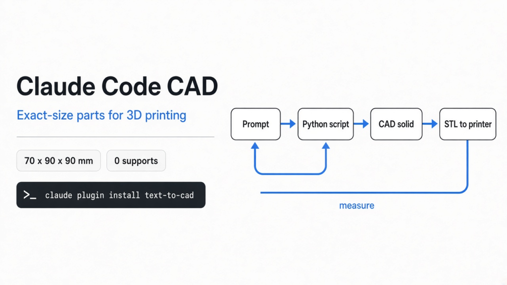
Here is the chain, one step at a time. You describe the part in everyday words. The agent writes a short Python script using build123d (a Python library for building CAD shapes with code). That script runs on Open CASCADE (a free CAD engine that does the real solid geometry math).
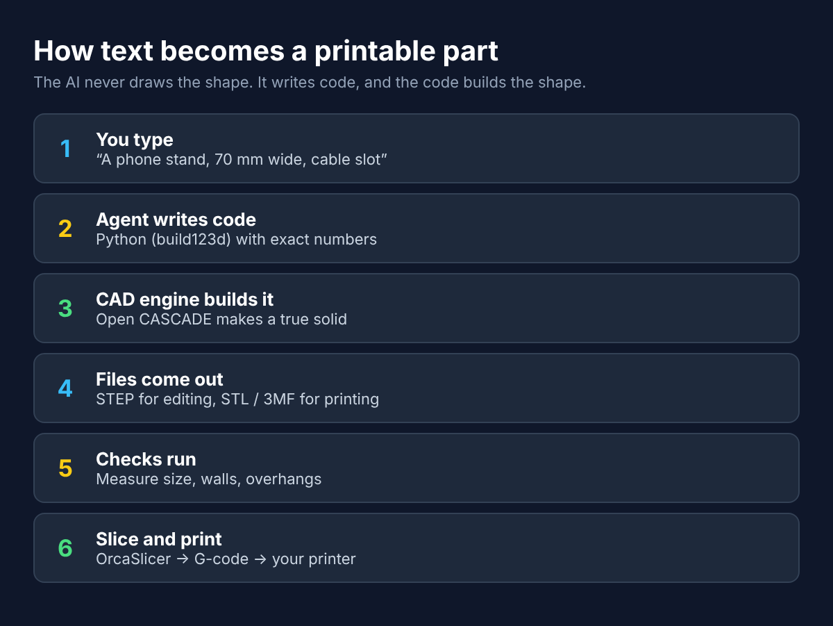
When the script runs, out come two kinds of files. STEP (the standard CAD file that keeps exact geometry, good for editing in other CAD apps) and STL or 3MF (mesh files your slicer reads). A slicer (an app that turns a 3D model into printer instructions) does the rest.
Then the part I liked most. The skill tells the agent to check its own work: measure the saved file, render a picture, and report what was not tested. That habit is what saved my test part, as you will see.
The plugin also carries skills for printability checks, 2D drawings for laser cutting, engineering drawing PDFs, slicing with OrcaSlicer, and sending a file to a Bambu Lab printer’s app. In that last one, the agent only opens the file. You pick the printer and press print yourself.
How do you install it in Claude Code?
Two commands, plus a tool called uv that you probably need to install first.
That is because the CAD side runs through uv (a fast Python package and version manager). Check you have it with uv --version. If not, install it from the uv website first.
Then, in your terminal:
claude plugin marketplace add earthtojake/text-to-cad#latest
claude plugin install text-to-cad@earthtojakeOnce both commands finish, restart Claude Code. The first start downloads the CAD runtime, so it needs internet. In my test, downloading the CAD runtime and running it the first time took about 12 seconds. The first picture render downloads a small headless browser too, about 114 MB, once.
You can also just ask your agent: “Install text-to-cad from https://github.com/earthtojake/text-to-cad“. The project recommends exactly that.
What happened when I made a phone stand?
It built a correct, printable stand in under a second per rebuild, and every size matched what I asked for.
So I gave it a real job. A desk phone stand, 70 mm wide, with a back plate leaning at 65 degrees. It needed a 14 mm front lip, room for a 12 mm thick phone in a case, and a 14 mm slot for the charging cable.
This is the full model script, written the way the skill tells the agent to write it. Every size is a named number at the top, so you can save it as src/phone_stand.py and change any of them:
from cadgen import build123d as bd
from cadgen import step, stl

WIDTH = 70.0        # along X
BASE_DEPTH = 90.0   # along Y
BASE_T = 5.0        # base plate thickness
BACK_LEN = 95.0     # length of the leaning back plate
BACK_T = 5.0
LEAN_DEG = 65.0     # back plate angle from the desk
LIP_H = 14.0        # front lip height
LIP_T = 5.0
PHONE_T = 12.0      # phone + case thickness the slot must take
CABLE_W = 14.0      # cable slot width


@step(out="../STEP/phone_stand.step")
@stl(out="../STL/phone_stand.stl")
def phone_stand():
    base = bd.Box(WIDTH, BASE_DEPTH, BASE_T, align=(bd.Align.CENTER, bd.Align.MIN, bd.Align.MIN))
    # front lip at the front edge (Y=0)
    lip = bd.Box(WIDTH, LIP_T, LIP_H + BASE_T, align=(bd.Align.CENTER, bd.Align.MIN, bd.Align.MIN))
    # back plate: starts behind the phone slot, leans backwards at LEAN_DEG
    back = bd.Box(WIDTH, BACK_T, BACK_LEN, align=(bd.Align.CENTER, bd.Align.MIN, bd.Align.MIN))
    back = back.rotate(bd.Axis.X, -(90 - LEAN_DEG))
    back = back.moved(bd.Location((0, LIP_T + PHONE_T, BASE_T - 1.0)))
    body = base + lip + back
    # cable slot through the lip and base front
    slot = bd.Box(CABLE_W, LIP_T + PHONE_T + 2, LIP_H + BASE_T + 2,
                  align=(bd.Align.CENTER, bd.Align.MIN, bd.Align.MIN)).moved(bd.Location((0, -1, -1)))
    body = body - slot
    # trim anything that dips below the desk
    body = body & bd.Box(400, 400, 400, align=(bd.Align.CENTER, bd.Align.CENTER, bd.Align.MIN)).moved(bd.Location((0, 50, 0)))
    body.label = "phone_stand"
    return body


if __name__ == "__main__":
    phone_stand()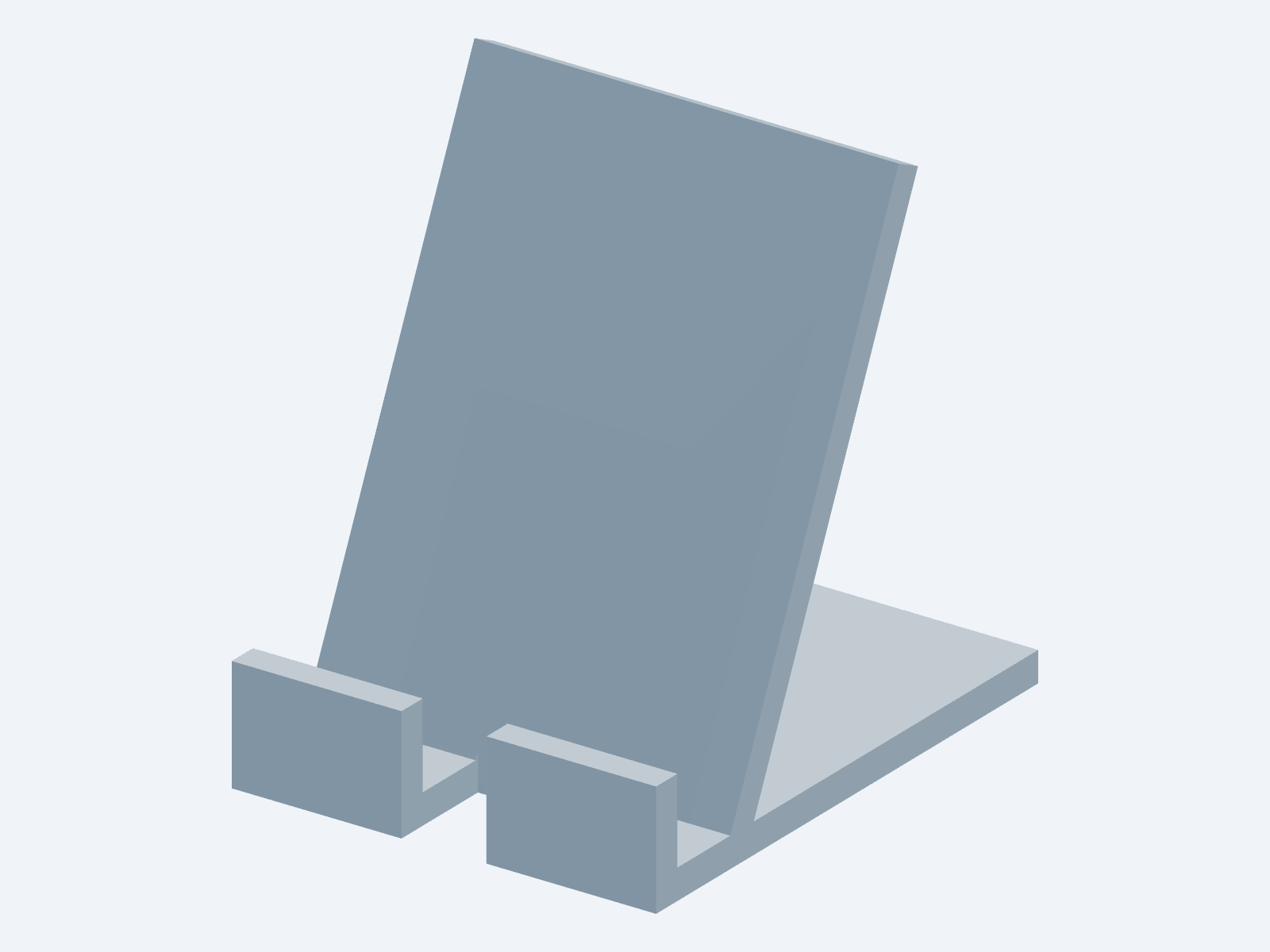
Running it wrote both files. The first build took about 10 seconds while the build helper warmed up. Every rebuild after that took about half a second.
Then I measured the saved STEP file instead of trusting my eyes:
- Valid solid: yes, one single body
- Size: 70 x 90 x 90.1 mm
- Volume: 66.6 cubic cm, about 83 g of PLA if printed fully solid
- Highest point: 57 mm back from the front edge, so the back leans away from you
That last line looks boring. It is the most important one in this post.
Why should you check the numbers, not the picture?
Because a 3D picture can lie about direction, and I believed it.
After the first build I looked at the angled render. The back plate looked like it was tipping forward, toward the lip. A stand that leans forward drops your phone on the desk.
So I “fixed” it. I flipped the lean angle and rebuilt.
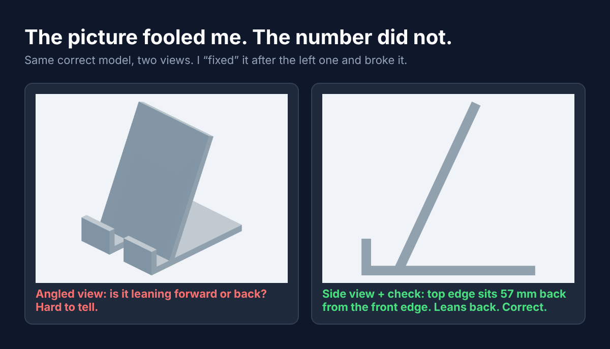
But the fix was the bug. My measurement script showed the part had grown from 90 mm deep to 113 mm, because the plate now stuck out past the front. The original was right all along. An angled view of flat plates has no depth cues (shading and shadows that tell you what is near and far), so your brain guesses.
I put the angle back and added one check: where is the highest point? 57 mm back from the front edge means it leans back. A side view confirmed it in one glance.
That is why the skill already warns about this: a mesh image does not prove exact sizes. Now I know why it says so. If you use text-to-cad, ask the agent for a side view and a measured number for anything that must face one way.
Will it actually print?
Yes. The printability check found zero overhangs and zero support material.
First, one printing idea you need. A 3D printer stacks melted plastic layer on layer. Each new layer needs something under it. If a surface leans too far, the plastic droops into the air.
The usual rule for home printers: a surface that rises at least 45 degrees from the build plate prints fine. Flatter than that, you need supports (extra throwaway plastic that holds up the leaning part while it prints).
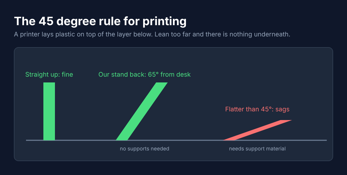
The dfam-check skill (DfAM means Design for Additive Manufacturing, the rules for shapes that print well) measured my STL in about 2 seconds:
| Check | Result | What it means for you |
|---|---|---|
| Watertight | Yes | No holes in the mesh, the slicer will not complain |
| Bodies | 1 | One piece, nothing floating |
| Thinnest wall | 5.0 mm | Strong, far above what a printer can make |
| Overhang area past 45 degrees | 0 | Prints without supports |
| Support volume | 0 | No cleanup, no wasted plastic |
Those zeros come from the angle. The back plate rises at 65 degrees from the desk, well above the 45 degree line, so every layer sits mostly on the one below it.
One honest limit: this tool measures facts, it does not slice or print. A real print can still fail on bed adhesion or a warped first layer. The check removes design mistakes, not printer problems.
What can’t text-to-cad do?
It is great for boxy, measurable parts. It will not turn a vague idea into a perfect product on its own.
Still, there are good reasons to stay with a normal CAD app. If you already know Fusion or Onshape, clicking a fillet may be faster than describing it. And organic shapes like figurines or faces are mesh territory, not this.
Here is what to expect:
- You must give real sizes. Measure your phone, your shelf, your screw. The agent cannot guess them
- You must review the result. The agent writes code that runs, not code that is always what you meant
- Setup needs uv and a first-run download
- It never starts a print by itself. You press print
- Complex assemblies take more back-and-forth than one simple bracket
If you are new to giving an agent a whole skill pack, read whether autoharness is worth it for Claude Code skills first. And if your agent loads many tools, keep an eye on which MCP servers waste tokens.
Who should use it?
Anyone who prints functional parts and is tired of redrawing a bracket for a 2 mm change.
Use it if you print mounts, holders, boxes, spacers and adapters. Those are shapes made of plates, holes and slots, and they need to fit something real. That is exactly where named numbers beat a sculpted mesh.
Skip it if you print miniatures or art. A text-to-3D mesh tool fits that job better.
If you want real pictures out of an agent instead of ASCII sketches, the same idea works for diagrams: how to make Claude Code draw real diagrams. And when the agent starts adding parts you never asked for, use this fix for Claude Code overengineering.
Get the plugin from the text-to-cad repo, and read the build123d docs if you want to edit the scripts yourself.
So start with one part you have printed before. Measure the old one, ask for the new one, and check the side view before you press print. Looking right is easy. Being right is the part you measure.
Common questions about text-to-cad
Is text-to-cad free?
Yes. It is open source under the MIT license, so personal and work use are both free. You still pay for whatever AI agent you run it in.
Can Claude Code make an STL file?
Yes. With text-to-cad installed, the agent writes a model script that exports STL, 3MF, GLB or STEP files you can open in any slicer.
Do I need to know CAD to use it?
No, but you need to know your sizes. Measure what the part must fit, give those numbers in your prompt, and check the measured result before printing.
Does text-to-cad work with Bambu Lab printers?
It can open a sliced file in Bambu Connect or an unsliced model in Bambu Studio. You choose the printer and start the print yourself.